


Цена по запросу
Отправить запрос
Наши менеджеры обязательно свяжутся с вами и уточнят условия заказа
Самовывоз.
Доставка по Москве и МО.
Доставка по России.
Внимание! В связи с нестабильным курсом валют, уточняйте цены у менеджеров отдела продаж.
Доставка по Москве и МО.
Доставка по России.
Внимание! В связи с нестабильным курсом валют, уточняйте цены у менеджеров отдела продаж.
Описание
DUO-LOCK; MaxiMet; Square End; 2 Flutes; Inch. MaxiMet; ABDF; Wiper Facet. Модульные концевые фрезы DUO-λOCK® • MaxiMet™
Особенности:
- Center cutting.
- Optimized for thin-wall applications.
- Wiper facet, special end gash, and flute geometry enable improved surface finishes.
- Standard items listed. Additional styles and coatings made-to-order.
Применение:
- Plunge Milling
- Ramping: Blank
- Slotting: Square End
- Side Milling/Shoulder Milling: Square End
- Corner Style: Square End
- Helix Angle: 45°
- Tool Dimensions: Flute Configuration: 2
| SAP Material Number | ISO Catalog Number | [D1] Effective Cutting Diameter | Adapter Style Machine Side | [CSMS] System Size Machine Side | [Z] Number of Flutes | [WF] Width of Flat | [L1] Gage Length | [D] Adapter / Shank / Bore Diameter | [AP1MAX] 1st Maximum Cutting Depth |
|---|---|---|---|---|---|---|---|---|---|
| 6151112 | ABDF0375Y2CU | 9.5250 | DUO-LOCK | DL10 | 2 | 8.0000 | 21.4000 | 9.125 | 14.2900 |
| 6151113 | ABDF0500Y2CU | 12.7000 | DUO-LOCK | DL12 | 2 | 9.5000 | 28.6000 | 12.2 | 19.0500 |
| 6151114 | ABDF0625Y2CU | 15.8750 | DUO-LOCK | DL16 | 2 | 13.0000 | 35.7000 | 15.375 | 23.8130 |
| 6151115 | ABDF0750Y2CU | 19.0500 | DUO-LOCK | DL20 | 2 | 16.0000 | 42.9000 | 18.55 | 28.5750 |
Tolerance:
| End Mill Tolerances | |
| D1 | tolerance e8 |
| 13/32 23/32" | -0,00126"/-0,00232" |
| 23/32 1-3/16" | -0,00157"/-0,00287" |
| 1-3/16" | -0,00197''/-0,00350'' |
Режимы резания:
MaxiMet; ABDF; Wiper Facet
| Material Group | 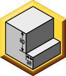 | 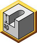 | 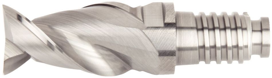 | |||||||||||||||
| Side Milling (A) and Slotting (B) | short | medium | long | Recommended feed per tooth (IPT = inch/th) for side milling (A). For slotting (B), reduce IPT by 20%. | ||||||||||||||
| A | B | adapter reach | D1 Diameter | |||||||||||||||
| K600 | K600 | K600 | ||||||||||||||||
| Cutting Speed vc SFM | Cutting Speed vc SFM | Cutting Speed vc SFM | frac. | 3/8 | 1/2 | 5/8 | 3/4 | |||||||||||
| ap | ae | ap | Min | Max | Min | Max | Min | Max | dec. | .3750 | .5000 | .6250 | .7500 | |||||
| N | 1 | 1.5 x D | 0.3 x D | 1.0 x D | 1640 | – | 6560 | 1312 | – | 3936 | 984 | – | 3936 | IPT | .0029 | .0038 | .0048 | .0057 |
| 2 | 1.5 x D | 0.3 x D | 1.0 x D | 1640 | – | 4920 | 1312 | – | 2952 | 984 | – | 2952 | IPT | .0023 | .0031 | .0038 | .0046 | |
| 3 | 1.5 x D | 0.3 x D | 1.0 x D | 1640 | – | 4920 | 1312 | – | 2952 | 984 | – | 2952 | IPT | .0020 | .0027 | .0033 | .0040 | |
| 4 | 1.5 x D | 0.3 x D | 1.0 x D | 1310 | – | 2460 | 1048 | – | 1476 | 786 | – | 1476 | IPT | .0020 | .0027 | .0033 | .0040 | |
| 5 | 1.5 x D | 0.3 x D | 1.0 x D | 820 | – | 3280 | 656 | – | 1968 | 492 | – | 1968 | IPT | .0026 | .0034 | .0043 | .0052 | |
| Material Group | | | 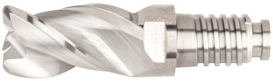 | |||||||||||||||
| Side Milling (A) and Slotting (B) | short | medium | long | Recommended feed per tooth (IPT = inch/th) for side milling (A). For slotting (B), reduce IPT by 20%. | ||||||||||||||
| A | B | adapter reach | D1 Diameter | |||||||||||||||
| K600 | K600 | K600 | ||||||||||||||||
| Cutting Speed vc SFM | Cutting Speed vc SFM | Cutting Speed vc SFM | frac. | 3/8 | 1/2 | 5/8 | 3/4 | |||||||||||
| ap | ae | ap | Min | Max | Min | Max | Min | Max | dec. | .375 | .500 | .6250 | .7500 | |||||
| N | 1 | 1.5 x D | 0.3 x D | 1.0 x D | 1640 | – | 6560 | 1312 | – | 3936 | 984 | – | 3936 | IPT | .0029 | .0038 | .0048 | .0057 |
| 2 | 1.5 x D | 0.3 x D | 1.0 x D | 1640 | – | 4920 | 1312 | – | 2952 | 984 | – | 2952 | IPT | .0023 | .0031 | .0038 | .0046 | |
| 3 | 1.5 x D | 0.3 x D | 1.0 x D | 1640 | – | 4920 | 1312 | – | 2952 | 984 | – | 2952 | IPT | .0020 | .0027 | .0033 | .0040 | |
| 4 | 1.5 x D | 0.3 x D | 1.0 x D | 1310 | – | 2460 | 1048 | – | 1476 | 786 | – | 1476 | IPT | .0020 | .0027 | .0033 | .0040 | |
| 5 | 1.5 x D | 0.3 x D | 1.0 x D | 820 | – | 3280 | 656 | – | 1968 | 492 | – | 1968 | IPT | .0026 | .0034 | .0043 | .0052 | |
Задать вопрос
Нужна консультация?
Наши специалисты ответят на любой интересующий вопрос
Задать вопрос
